
Minnesota Administrative Rules
1513.0450 PRESSURE RELIEF VALVES.
Subpart 1.
Start to discharge pressure; relieving capacity.
The tank must be provided with a system of one or more pressure relief valves which can limit the tank pressure below 115 percent (110 percent if only one pressure relief valve is used) of the design pressure during operational emergency conditions other than fire and below 121 percent of the design pressure during operational emergency conditions that include fire. One of the pressure relief valves must be set to start to discharge at a pressure not in excess of the design pressure of the tank and all other pressure relief valves needed to limit the tank pressure below 115 percent (110 percent if only one pressure relief valve is used) of the design pressure during operational emergency conditions other than fire must be set to discharge at a pressure not in excess of 105 percent of the design pressure. All additional pressure relief valves needed to limit the tank pressure below 121 percent of the design pressure during operational emergency conditions including fire must be set to start to discharge at a pressure not in excess of 110 percent of the design pressure.
Subp. 2.
Total relieving capacity.
The pressure relief valves set to discharge below 105 percent of the design pressure of the tank must have a total relieving capacity in excess of the relieving capacity required to handle operating emergency conditions listed in item A. The total relieving capacity of all the pressure relief valves in the system must be the larger requirement of item A or B.
B.
Either one of the following formulas for fire exposure:
(1)
for valve manufacturers who classify valves on the basis of the weight of the vapors to be relieved:
| 34,500 F A0.82 | ||||
| W | = | _ | ||
| L | ||||
(2)
For valve manufacturers who classify valves on the basis of air flow:
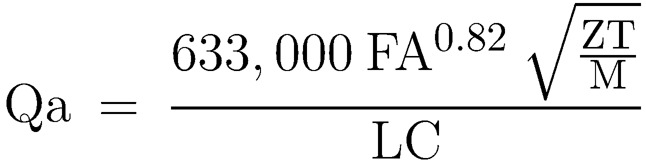
Where:
W = weight of vapors to be relieved in pounds/hour at relieving conditions
Qa = air flow in cubic feet per minute at standard conditions (60 degrees Fahrenheit and 14.7 psi)
F = fireproofing credit. Use F = 1.0 except when an approved fireproofing material of recommended thickness is used, in which case use F = 0.2
A = total surface area in square feet up to 25 feet above grade or to the equator of a sphere, whichever is greater
Z = compressibility factor of ammonia at relieving condition (if not known, use Z = 1.0)
T = temperature in degrees R (460 + temperature in degrees Fahrenheit of gas at relieving conditions)
M = molecular weight = 17 for ammonia
L = latent heat of ammonia at relieving conditions in Btu per pound
C = constant based on relation of specific heats
(C may be obtained from the following table)
(If K is not known, use C = 315)
| K | C | K | C | K | C |
| 1.00 | 315 | 1.26 | 343 | 1.52 | 366 |
| 1.02 | 318 | 1.28 | 345 | 1.54 | 368 |
| 1.04 | 320 | 1.30 | 347 | 1.56 | 369 |
| 1.06 | 322 | 1.32 | 349 | 1.58 | 371 |
| 1.08 | 324 | 1.34 | 351 | 1.60 | 372 |
| 1.10 | 327 | 1.36 | 352 | 1.62 | 374 |
| 1.12 | 329 | 1.38 | 354 | 1.64 | 376 |
| 1.14 | 331 | 1.40 | 356 | 1.66 | 377 |
| 1.16 | 333 | 1.42 | 358 | 1.68 | 379 |
| 1.18 | 335 | 1.44 | 359 | 1.70 | 380 |
| 1.20 | 337 | 1.46 | 361 | 2.00 | 400 |
| 1.22 | 339 | 1.48 | 363 | 2.20 | 412 |
| 1.24 | 341 | 1.50 | 364 |
| Cp | |||
| Where K = | _ | at atmospheric conditions | |
| Cv | |||
| and Cp = Specific heat of vapor at constant pressure |
| Cv = Specific heat of vapor at constant volume |
Subp. 3.
Shut-off valves.
Shut-off valves of adequate flow capacity may be provided and used to facilitate inspection and repair of pressure relief valves. If a shut-off valve is provided, it must be arranged so that it can be locked or sealed open and it may not be closed except by an authorized person who must remain there while the valve remains closed and who must again lock or seal the valve open when leaving the station.
Subp. 4.
Noncorrosive stacks; discharge lines.
Pressure relief valves must comply with items A and B.
A.
If noncorrosive stacks are used, they must be suitably designed to prevent obstruction by rain, snow, ice, or condensate. The outlet size may not be smaller than the nominal size of the pressure relief valve outlet connection.
B.
Discharge lines may be used if desired. Multiple pressure relief valves on the same storage unit may be run into a common discharge header. The discharge line and header must be designed to accommodate the maximum flow and back pressure not exceeding ten percent of the design pressure of the storage container. This back pressure must be included in the 120 percent total maximum pressure given in subpart 1. No other container or system may exhaust into this discharge line or header. The vent lines must be installed to prevent accumulation of liquid in the lines.
Subp. 5.
Atmospheric storage.
Atmospheric storage must be provided with vacuum breakers of adequate capacity to respond to anticipated rates of liquid withdrawal and to rapid atmospheric changes so as to avoid damage to the container. Ammonia gas may be used to provide a pad.
Subp. 6.
Discharge to open air.
Pressure relief valves used to protect other systems at refrigerated storage installations must discharge to the open air.
Statutory Authority:
MS s 18C.121
History:
21 SR 277
Published Electronically:
January 27, 2023
Official Publication of the State of Minnesota
Revisor of Statutes